If you need hydraulic solutions according to standards for your project, Aircontrol offers to manufacture reliable, standardised hydraulic cylinders with the guarantee that we get from working with high quality components. Our professionals always work on the standard Aircontrol hydraulic cylinders with the maximum guarantees, and within deadlines set to meet your needs.
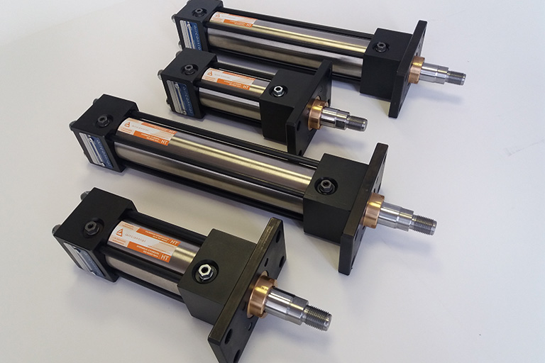
We produce HR series, ISO 6020/1 cylinders without tie rods and available in diameters of 25mm to 320mm, with pressure of up to 160 bar. We have cylinders available with a normal or reinforced piston rod, and with standard, high temperature or low friction seals. We work with HT series, ISO 6020/2 cylinders in diameters of 25mm to 200mm, with pressure of up to 160 bar. Select if you are looking for compact cylinders with a normal or reinforced piston rod.
We can also offer you the HV series, ISO 3320/2 cylinders for light applications, in diameters of 25mm to 320mm, and with pressure of up to 160 bar.
FAQs about hydraulic cylinders
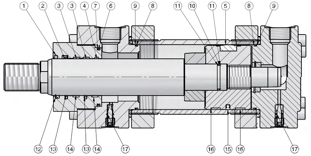
A hydraulic cylinder is a system that transforms the energy of a pressurised hydraulic fluid into linear movement. To achieve this transformation, the hydraulic cylinder uses a hydraulic piston that moves up and down inside a casing, transferring the pressure from the hydraulic fluid to a piston rod, which is the element that transmits the mechanical force. The hydraulic cylinder also has sealing caps and seals that ensure it is kept airtight.
The AirControl hydraulic cylinders are basically made on F-1140 steel, although other materials and finishes are available, depending on the client’s needs.
The next section shows the elements that make up a hydraulic cylinder, in this case ISO 6020/2.
There is a wide variety of hydraulic cylinders available, either because of their specific application or because of the different standards they must meet.
At AirControl, we have hydraulic cylinders that meet the requirements of ISO 6020/1, ISO 6020/2 or ISO 3320 standards, which are compatible with different manufacturers and hydraulic cylinders, according to the different applications: bucket, steering, suspension, lift, etc.
Furthermore, depending on their characteristics, there are also single-acting, double-acting, double piston rod, telescopic, round, tie rod hydraulic cylinders… without overlooking special or customised hydraulic cylinders that can reach pressures of up to 300 bar, with test pressures of up to 400 bar.
Single-acting cylinders differ from other cylinders in that they only have one fluid inlet, and they generate compressed linear movement in one single direction. This direction may be the inlet or the outlet of the piston rod, and the return is usually made with a spring or with the weight of the system itself, among others.
Double-acting cylinders are different from single-acting cylinders in that they have two inlets for the fluid, and they can generate movement in both directions. In this type of cylinder, the force that is generated in each direction is smaller given that the surface in contact with the fluid is smaller in the chamber housing of the piston rod than in the other chamber
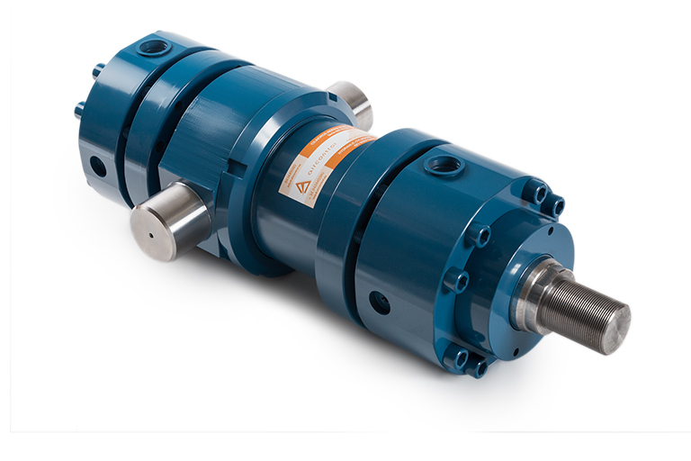
Double rod cylinders can be single or double-acting, but in this case, they will have two piston rods with their two respective guide caps. In this type of cylinder, force applied in both chambers would be the same.
Telescopic hydraulic cylinders have the advantage of achieving long runs or strokes with a relatively short cylinder length. They can be 2-stage or multi-stage, which means that they would have several “rods” inside in the form of different diameter tubes which fit into each other. They are usually single-acting cylinders, although double-acting cylinders are possible, despite the complexity of their design.
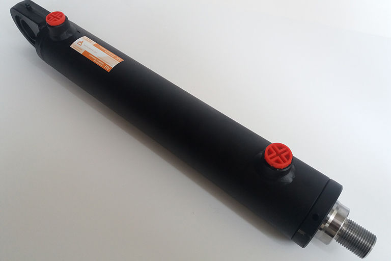
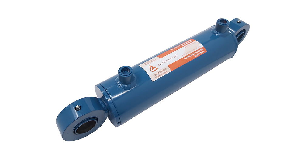
Welded round cylinders are a cost-effective solution due to their simplicity, and they are very common in agriculture and mobile hydraulics. The rear cover is welded to the casing with a special welding to ensure tightness sealed and resistance at high pressures.
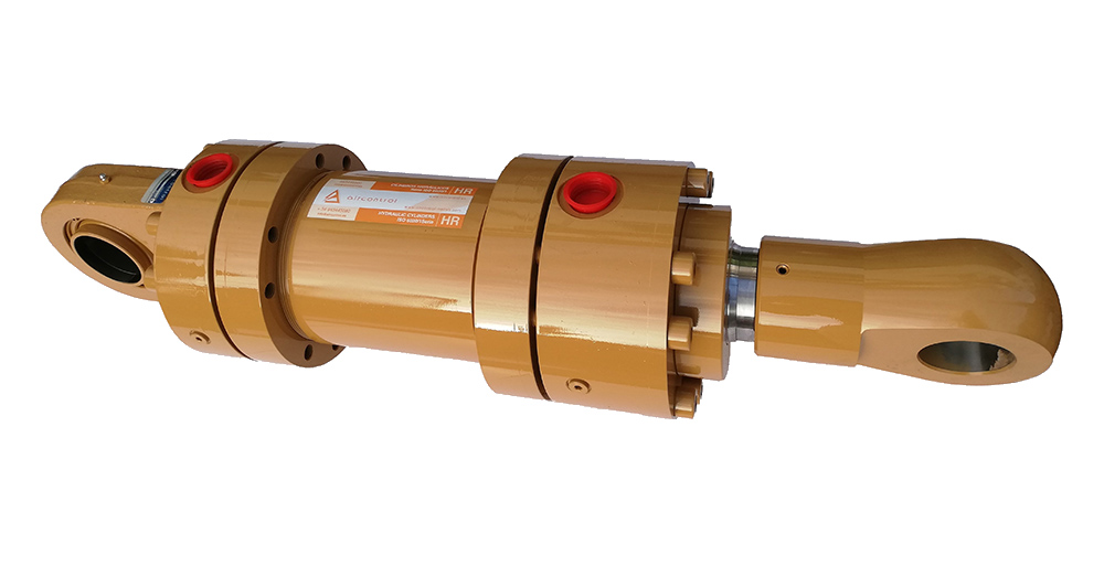
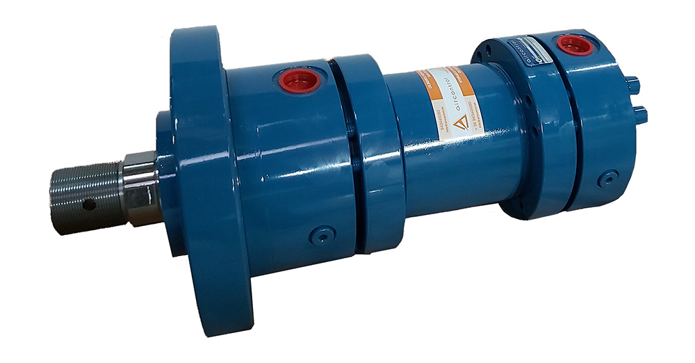 AirControl cylinders according to ISO 6020/1 standard
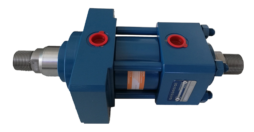
The cylinders according to ISO standards are standardised and interchangeable between different manufacturers. The most common standards are: cylinders according to ISO 6020/1, which are cylinders with round caps that are mounted with some screws that counter pressure between the caps and the retaining washers, and do not require tie rods; and the cylinders according to ISO 6020/02, which are similar to a pneumatic cylinder, given that the caps are held on with tie rods and nuts.
Furthermore, at AirControl we can customise any of the above mentioned cylinders, both in terms of dimensions and materials, for different of environmental conditions or specific applications.
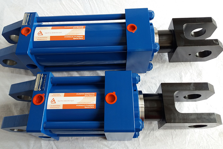
The hydraulic cylinders come with different fixing elements that enable the cylinder to be adapted to meet the client’s specific needs.
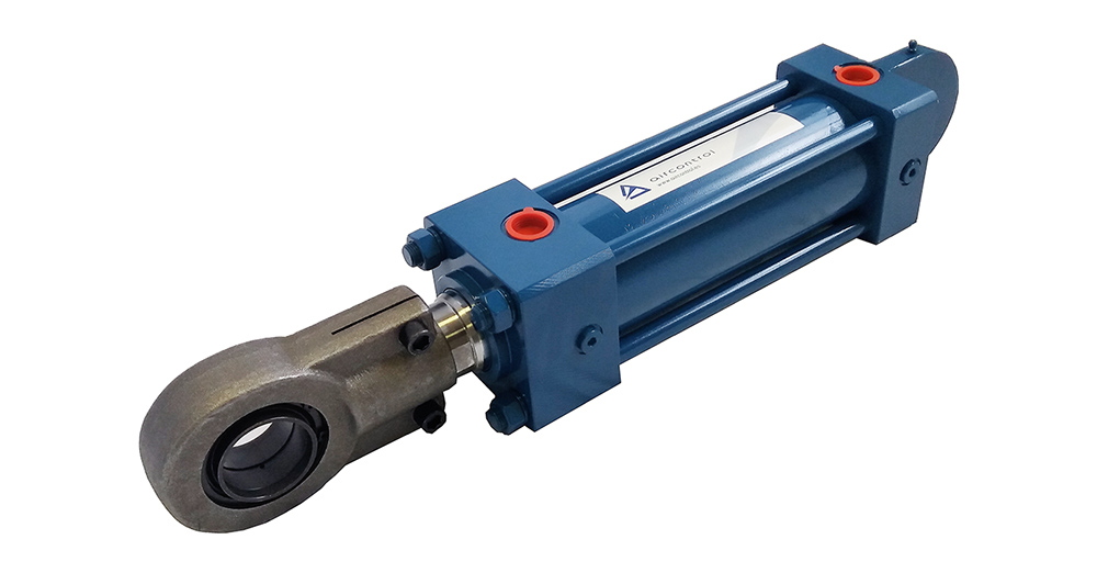 AirControl cylinders according to ISO 6020/02 standard
A hydraulic cylinder consists of some basic elements, such as the casing, the caps, the piston and the piston rod, as well as a range of seals that ensure the hydraulic cylinder is properly sealed.
They work on the basis of pressurising a hydraulic oil or fluid in each of the two chambers of the hydraulic cylinder, which are separated by the piston. Depending on which of the two chambers we hydraulically pressurise, the piston and the piston rod connected to it will make the cylinder exert a pushing or pulling force.
Depending on the diameter of the hydraulic cylinder and on the fluid pressure, we will achieve a greater or lesser force. In order to know how much force a hydraulic cylinder exerts, we must apply the following formula:
F = P * A
Where the parameters are as follows:
Another factor that influences on how a hydraulic cylinder works is the flow rate of the fluid. The flow directly affects the speed at which the piston rod will move. The higher the flow, the higher the speed.
Cushioning is also an important factor in hydraulic cylinders. At both ends of the cylinder, there is a system installed to slow down the piston, to prevent it from hitting the caps, and from transmitting the hit to the system where the cylinder is assembled. The cushioning must be manually adjusted using an adjustment screw incorporated in the cylinder, seeing as, in each application, the cylinder will behave differently depending on the working conditions in each case.
Our catalogue of hydraulic cylinders includes a wide variety of fixing elements that facilitate the hydraulic cylinder's installation in the application, and allow the cylinder to be adapted to meet the client’s specific requirements.
These fixing systems can be integrated into the hydraulic cylinder’s construction, or they can be attached to the base cylinder.
We offer the following mountings for the ISO 6020/1, HR series:
We offer the following fastenings for the ISO 6020/2, HT series:
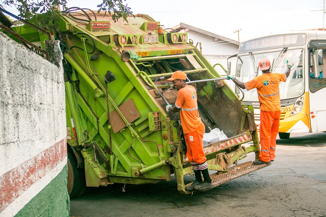
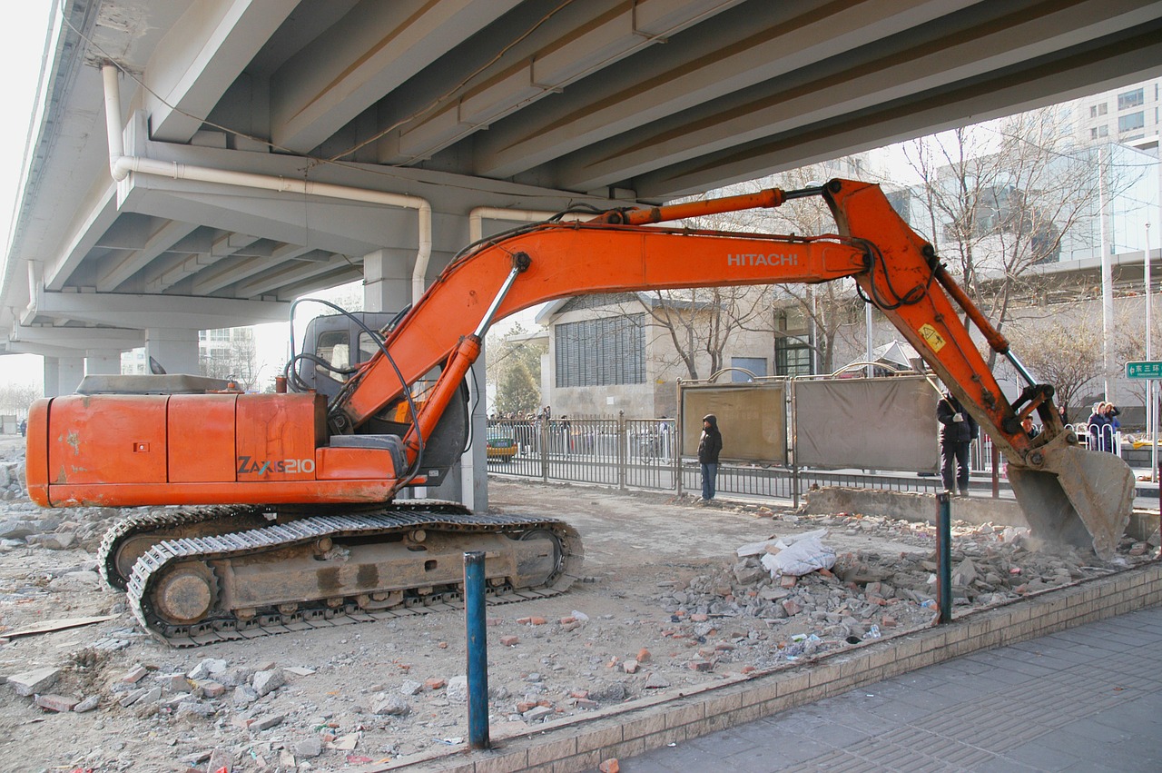
The applications for a hydraulic cylinder can essentially be divided into 5 main groups: agriculture, mobile equipment, industrial equipment, public works machinery, and machinery for environmental management.
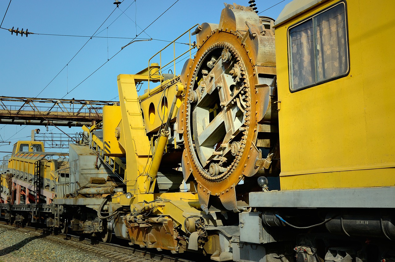
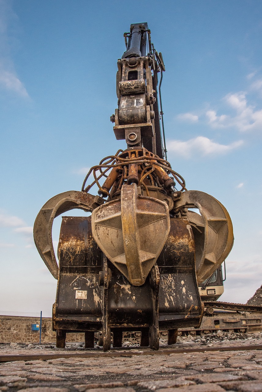
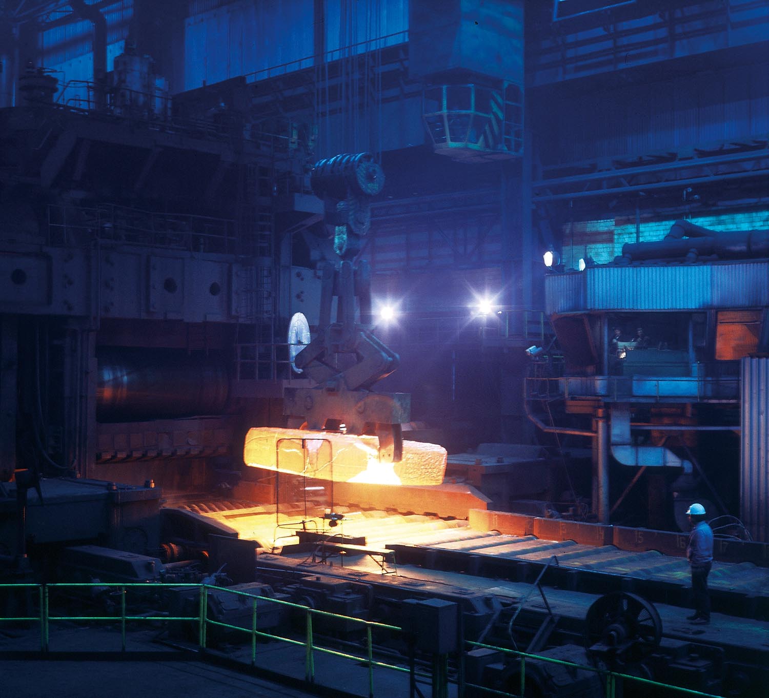
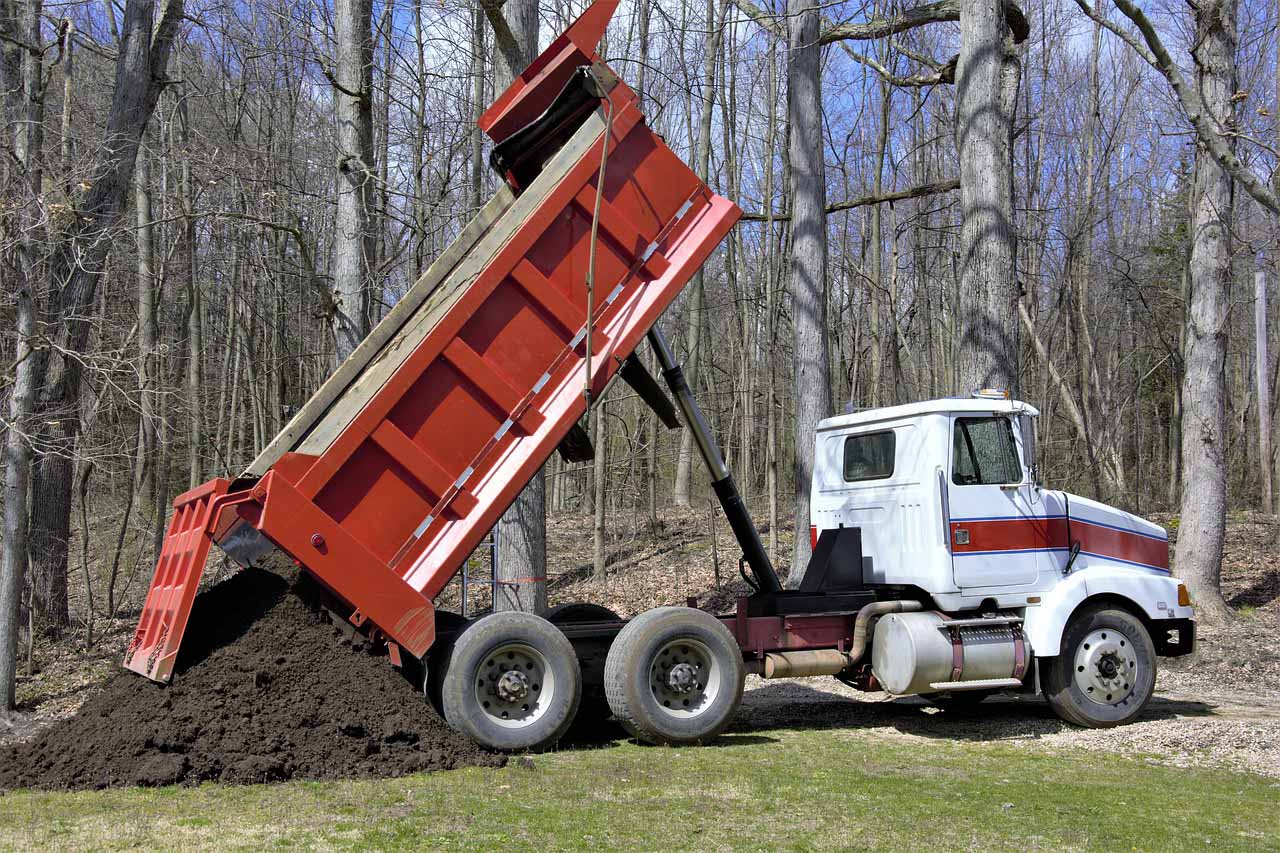
At AirControl we manufacture hydraulic cylinders for any of these applications, and we are particularly prominent in sectors such as the steel industry, mobile cranes, forestry machinery, presses, truck bodies, hydraulic cranes, strimmers, lifting platforms, buckets, machinery for the paper industry, railways, car industry, forges, agricultural machinery, industrial folding machines, special machinery, recycling equipment, industrial washing machines, foundry, welding machines, MOT machinery, refuse collection trucks, waste trucks, polyp grabbers, tippers, construction machinery, diggers, hydraulic bollards...


Hydraulic cylinders require minimum maintenance. Except in particularly challenging applications, or due to extraordinary causes unrelated to its operations. As long as the cylinder is being used under the recommended conditions, only its seals will need replacing.
A correctly sized and maintained hydraulic installation will extend the life of both the hydraulic cylinder, and the rest of its components, such as motors, valves, etc.
The hydraulic fluid must be selected in accordance to the application. Temperature, operation speed, resistance and viscosity must all be taken into account, among other factors. All this will enable the hydraulic cylinder to work correctly. Furthermore, proper control over the cleaning and levels of hydraulic fluid filling will not only increase the hydraulic cylinder’s service life, but also that of the entire installation.
At AirControl, we recommend regular preventive checks of the cylinders. Checking that the connections are properly fastened, we will avoid accidents due to leaks. It is also essential that the cylinder is kept aligned with respect to the point where the force is to be applied, given that any lateral loads may cause damage, such the piston rod buckling, breaking the seals, breaking the fastenings, etc.
We also recommend always having a kit of seals in stock to prevent machine stoppage.
At AirControl, we can provide clients with a maintenance and repair manual, as well as the necessary advice for the replacement of the seals.
If you already know the specific features or dimensions of the cylinder you require, you can browse our catalogue and choose the option that best suits your needs. If you do not, our staff will advise you in choosing the hydraulic cylinder that is most suitable for your application or, if necessary, in designing the hydraulic cylinder that best suits your needs.
The steps to follow when choosing a hydraulic cylinder are as follows:
How much force do we need to move? It is important to know what the cylinder is going to need to move and what the weight of that element is. We must define the hydraulic cylinder’s capacity according to these factors, setting a nominal standard pressure of 150 bar. This is the recommended pressure for standard cylinders, although they can support pressures of up to 240 bar at specific moments. Below you will find a table to help you choose the most suitable diameter:
| Ø Piston mm | Ø Rod mm | Work area | 50 bar | 100 bar | 150 bar | 200 bar | |||||
|---|---|---|---|---|---|---|---|---|---|---|---|
| Push | Pull | Push | Pull | Push | Pull | Push | Pull | Push | Pull | ||
| cm² | cm² | kN | kN | kN | kN | kN | kN | kN | kN | ||
| 25 | 14 | 4,91 | 3,37 | 2,45 | 1,68 | 4,41 | 3,37 | 7,36 | 5,05 | 9,82 | 6,74 |
| 18 | 2,36 | 1,18 | 2,36 | 3,55 | 4,73 | ||||||
| 32 | 18 | 8,04 | 5,50 | 4,02 | 2,75 | 8,04 | 5,50 | 12,06 | 8,25 | 16,08 | 11,00 |
| 22 | 4,24 | 2,12 | 4,24 | 6,36 | 8,48 | ||||||
| 40 | 22 | 12,57 | 8,77 | 6,28 | 4,38 | 12,57 | 8,76 | 18,85 | 13,15 | 25,13 | 17,53 |
| 28 | 6,41 | 3,20 | 6,41 | 9,61 | 12,82 | ||||||
| 50 | 28 | 19,63 | 13,48 | 9,82 | 6,74 | 19,63 | 13,48 | 29,45 | 20,22 | 39,27 | 26,95 |
| 36 | 9,46 | 4,73 | 9,46 | 14,18 | 18,91 | ||||||
| 63 | 36 | 31,17 | 20,99 | 15,59 | 10,50 | 31,17 | 20,99 | 46,76 | 31,49 | 62,34 | 41,99 |
| 45 | 15,27 | 7,63 | 15,27 | 22,90 | 30,54 | ||||||
| 80 | 45 | 50,27 | 34,36 | 25,13 | 17,18 | 50,26 | 34,36 | 75,40 | 51,54 | 100,53 | 68,72 |
| 56 | 25,64 | 12,82 | 25,64 | 38,45 | 51,27 | ||||||
| 100 | 56 | 78,54 | 53,91 | 39,27 | 26,95 | 78,54 | 53,91 | 117,81 | 80,86 | 157,08 | 107,82 |
| 70 | 40,06 | 20,03 | 40,05 | 60,08 | 80,11 | ||||||
| 125 | 70 | 122,72 | 84,23 | 61,36 | 42,12 | 122,72 | 84,23 | 184,08 | 126,35 | 245,43 | 168,47 |
| 90 | 59,10 | 29,55 | 59,10 | 88,65 | 118,20 | ||||||
| 160 | 90 | 201,06 | 137,44 | 100,53 | 68,72 | 201,06 | 137,44 | 301,59 | 206,16 | 402,12 | 274,89 |
| 110 | 106,03 | 53,01 | 106,03 | 159,04 | 212,06 | ||||||
| 200 | 110 | 314,16 | 219,13 | 157,08 | 109,56 | 314,16 | 219,12 | 471,23 | 328,69 | 628,31 | 438,25 |
| 140 | 160,22 | 80,11 | 160,22 | 240,33 | 320,44 | ||||||
| 250 | 140 | 490,87 | 336,94 | 245,43 | 168,47 | 490,87 | 336,93 | 736,30 | 505,40 | 981,74 | 673,86 |
| 180 | 236,40 | 118,20 | 236,40 | 354,60 | 472,80 | ||||||
| 320 | 180 | 804,25 | 549,78 | 402,12 | 274,89 | 804,24 | 549,77 | 1.206,36 | 824,66 | 1.608,48 | 1.099,55 |
| 220 | 424,12 | 212,06 | 424,11 | 636,17 | 848,22 | ||||||
| Ø Piston mm | Ø Rod mm | Work area | 50 bar | 100 bar | 150 bar | 200 bar | |||||
|---|---|---|---|---|---|---|---|---|---|---|---|
| Push | Pull | Push | Pull | Push | Pull | Push | Pull | Push | Pull | ||
| cm² | cm² | kN | kN | kN | kN | kN | kN | kN | kN | ||
| 25 | 12 | 4,91 | 3,78 | 2,45 | 1,89 | 4,91 | 3,78 | 7,36 | 5,67 | 9,82 | 7,56 |
| 18 | 2,36 | 1,18 | 2,36 | 3,55 | 4,73 | ||||||
| 32 | 14 | 8,04 | 6,50 | 4,02 | 3,25 | 8,04 | 6,50 | 12,06 | 9,75 | 16,08 | 13,01 |
| 22 | 4,24 | 2,12 | 4,24 | 6,36 | 8,48 | ||||||
| 40 | 18 | 12,57 | 10,02 | 6,28 | 5,01 | 12,57 | 10,02 | 18,85 | 15,03 | 25,13 | 20,04 |
| 28 | 6,41 | 3,20 | 6,41 | 9,61 | 12,82 | ||||||
| 50 | 22 | 19,63 | 15,83 | 9,82 | 7,92 | 19,63 | 15,83 | 29,45 | 23,75 | 39,27 | 31,67 |
| 36 | 9,46 | 4,73 | 9,46 | 14,18 | 18,91 | ||||||
| 63 | 28 | 31,17 | 25,01 | 15,59 | 12,51 | 31,17 | 25,01 | 46,76 | 37,52 | 62,34 | 50,03 |
| 45 | 15,27 | 7,63 | 15,27 | 22,90 | 30,54 | ||||||
| 80 | 36 | 50,27 | 40,09 | 25,13 | 20,04 | 50,26 | 40,09 | 75,40 | 60,13 | 100,53 | 80,17 |
| 56 | 25,64 | 12,82 | 25,64 | 38,45 | 51,27 | ||||||
| 100 | 45 | 78,54 | 62,64 | 39,27 | 31,32 | 78,54 | 62,63 | 117,81 | 93,95 | 157,08 | 125,27 |
| 70 | 40,06 | 20,03 | 40,05 | 60,08 | 80,11 | ||||||
| 125 | 56 | 122,72 | 98,09 | 61,36 | 49,04 | 122,72 | 98,09 | 184,08 | 147,13 | 245,43 | 196,17 |
| 90 | 59,10 | 29,55 | 59,10 | 88,65 | 118,20 | ||||||
| 160 | 70 | 201,06 | 162,58 | 100,53 | 81,29 | 201,06 | 162,58 | 301,59 | 243,86 | 402,12 | 325,15 |
| 110 | 106,03 | 53,01 | 106,03 | 159,04 | 212,06 | ||||||
| 200 | 90 | 314,16 | 250,54 | 157,08 | 125,27 | 314,16 | 250,54 | 471,23 | 375,81 | 628,31 | 501,08 |
| 140 | 160,22 | 80,11 | 160,22 | 240,33 | 320,44 | ||||||
We are going to determine the cylinder stroke according to the distance over which we need to carry out the linear movement. This distance is usually determined in millimetres or in inches, depending on the regulations of each country in question.
The piston rod diameter is critical absorbing radial forces and preventing buckling. To define, its size we must bear in mind the length of the cylinder, because the longer the length of the cylinder, the greater the risk of buckling, and the force the cylinder needs to exert. With these two variables and the chart that we give you, you can work out the rod diameter that best suits your application.
The choice of hydraulic oil is a crucial factor in hydraulic cylinders. There are different types of oil available, depending on the working conditions:
Synthetic oils are suitable in extreme conditions, where temperatures change very quickly and where the pressures are very high.
Mineral oils are the most suitable oil to use in most applications, due to their versatility and cost.
This is the least used and is usually used in applications where there is a fire hazard or where even the slightest risk of fire cannot be tolerated. In terms of costs, they come somewhere in the middle, between the two previous oils.
At AirControl, the standard material used to manufacture our hydraulic cylinders is F-1140 structural steel, but depending on the client’s requirements, cylinders can be made in stainless steel or even with an aluminium casing, in those cases where magnetic sensors are required.
There are different types of seals. The most commonly used are those made of PU (polyurethane), although at AirControl we also offer low friction seals or seals for high temperatures.
In oleo-hydraulic systems, oil is of vital importance and in addition to being the means of transmission of power, forces and movements, it fulfils other functions such as:
The detergent action is produced when the aforementioned hydraulic fluid drags the contaminants from the circuit and carries them to the filter installed in the return pipe.
When the oil passes through the different throttles in the oleo-hydraulic system, its friction with the walls of the pipes and elements, together with the viscosity of the oil, causes a temperature increase. This temperature is then transferred to the elements, and part of the oil-hydraulic energy is transformed into heat. If the oil exceeds the maximum working temperature, it starts to deteriorate, so that temperature will need to be lowered and supervised to prevent a rapid reduction in its service life. An unusual increase in temperature will damage the elastomers that are used in the various seals and sealing elements of the hydraulic circuit, including the cylinder.
Depending on the size of the oleo-hydraulic system, the oil, before reaching the tank, may pass through a heat exchanger to lower its temperature. In other situations, the size of the tank is oversized to store a larger volume of oil, sufficient to dissipate the temperature of the hydraulic oil on its return to the tank.
When the oil passes through some throttles, air bubbles are produced and generate unwanted foam in the oleo-hydraulic system. The oil carries these bubbles to the tank where, thanks to the deflector plate, they dissipate.
Finally, due to the oil’s physical-chemical properties, it sticks to the surfaces which it comes into direct contact, and it forms a layer that helps to lubricate them, thus reducing the friction and consequently, wear and tear.
Another factor to control is the moisture in the environment where the oleo-hydraulic system is operating. As it condenses inside the tank and mixes with the oil, it forms an emulsion that deteriorates the different components. This can be avoided by selecting oils with anti-emulsifiers and/or antioxidants, as well as by controlling the moisture in the air that goes into the tank.
It is easy to see if the oil has been emulsified, as corrosion will appear on the surfaces of some oleo-hydraulic components.
An oil that has recently been produced by a manufacturer is not completely clean, and certain particles may be found in it. The ISO 4406 standard classifies oils with three pairs of digits. The first pair refers to the amount of particles larger than 4 microns. The second pair refers to the amount of particles larger than 6 microns. And the third pair refers to the amount of particles larger than 14 microns.
The selection of the oil according to the ISO 4406 standard, shall be made taking into account not only the components of the hydraulic circuit but also the type of internal mechanism used in the oleo-hydraulic pump and the type of valve, considering if they are conventional, proportional or servo valve. This is done to ensure a longer service life of these components.
The hydraulic oil must be analysed in a specialised laboratory and not just changed on the basis of working hours, as usually recommended by some manufacturers. It is advisable to monitor the condition of the oil and to implement a filter maintenance and replacement plan, taking into account that, when the oil is changed, it is important to use the one specifically recommended for the type of machine, and no other, avoiding mixing.
The main reasons for using a hydraulic cylinder instead of a pneumatic one are varied.
A hydraulic cylinder provides more force than a pneumatic cylinder of the same diameter or piston size. The pressures that the hydraulic fluid can reach are much higher than with compressed air. Hydraulic cylinders are designed to work at these pressures and the force they can develop is multiplied.
A normal working pressure for a pneumatic cylinder can be around 6 bar, with a maximum of 10 bar. A hydraulic cylinder can work at pressures of around 100 bar, reaching 160 bar or even higher. This means that the force developed by a hydraulic cylinder easily exceeds that of a pneumatic cylinder with the same dimensions.
Another advantage of hydraulic cylinders is that, thanks to the lower compressibility of the hydraulic fluid, the speed control of a hydraulic cylinder is much more precise than that of a pneumatic cylinder. This characteristic of the hydraulic fluid also gives other advantages, such as the fact that the fixing or positioning of a load with a hydraulic cylinder is much easier and safer than with a pneumatic cylinder.
Bearing this in mind, we will use a hydraulic cylinder when we have space limitations to install a pneumatic cylinder, when we want greater control over the speed or positioning of the load, or when we want greater safety when it comes to keeping that load in position.
We will use a pneumatic cylinder when the necessary forces are lower, when we need greater speed and repeatability, or when the movement of the load does not need to be so precise.
We will also give preference to use a pneumatic cylinder over a hydraulic cylinder when, even if the conditions of the previous paragraph are not met, the tooling or the system do not require continuous use and it is easier to find a compressed air connection in the installation.
In most autonomous facilities with continuous use, it will be easier and more compact to use a complete hydraulic installation with pump, valves, hydraulic cylinder and other components, rather than a pneumatic system.